Sia
Question 1
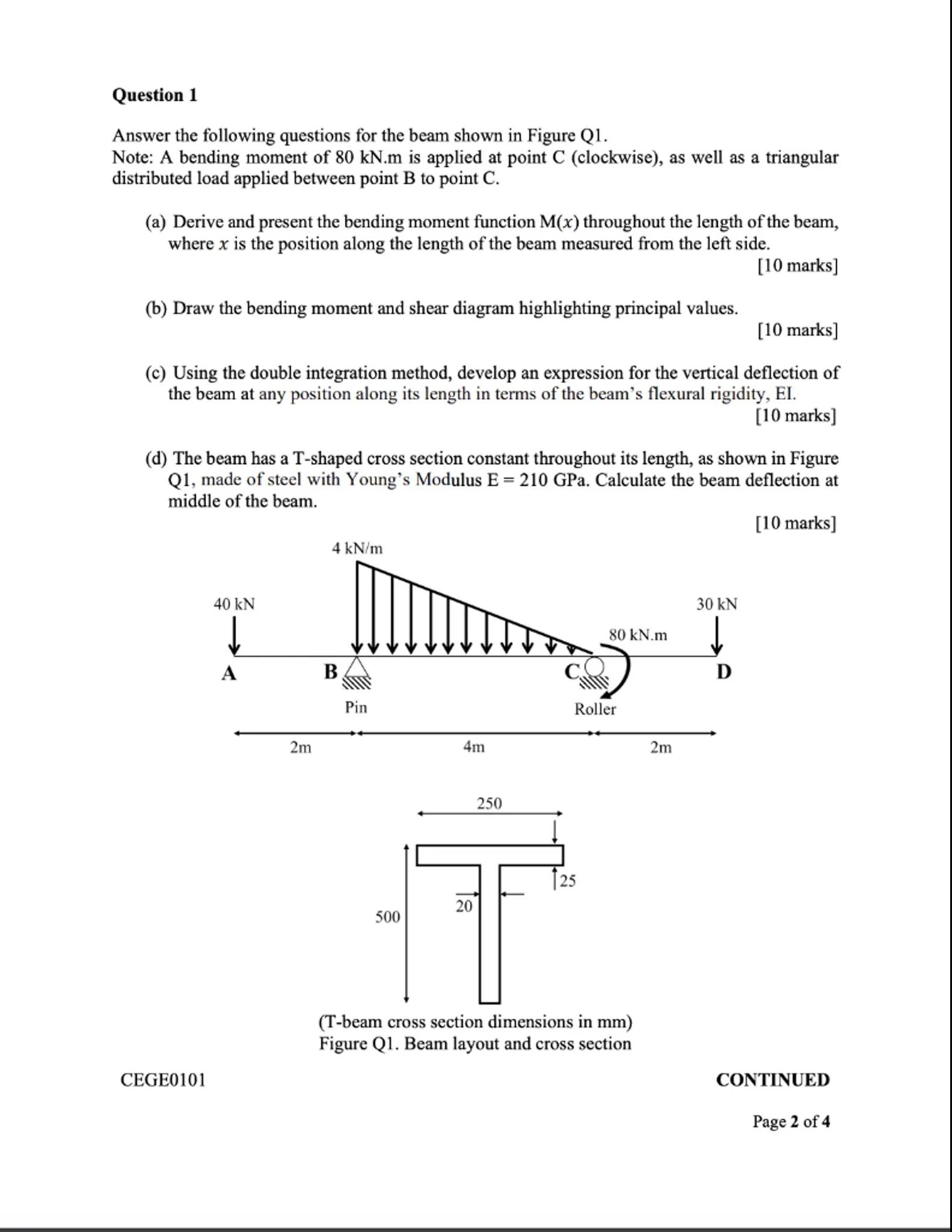
Answer the following questions for the beam shown in Figure Q1.
Note: A bending moment of is applied at point C (clockwise), as well as a triangular distributed load applied between point B to point C .
(a) Derive and present the bending moment function throughout the length of the beam, where is the position along the length of the beam measured from the left side.
[10 marks]
(b) Draw the bending moment and shear diagram highlighting principal values.
[10 marks]
(c) Using the double integration method, develop an expression for the vertical deflection of the beam at any position along its length in terms of the beam's flexural rigidity, EI.
[10 marks]
(d) The beam has a T-shaped cross section constant throughout its length, as shown in Figure Q1, made of steel with Young's Modulus E . Calculate the beam deflection at middle of the beam.
[10 marks]
(T-beam cross section dimensions in mm )
Figure Q1. Beam layout and cross section
CEGE0101
CONTINUED
Page 2 of 

Answer from Sia
Posted over 1 year ago
Solution
a
To derive the bending moment function along the beam, we need to consider the effects of the applied loads. The concentrated load of at point A creates a moment about point B, and the distributed load of between points B and C contributes to the bending moment as well. The moment at any section can be expressed as:
where is the moment due to the load at A, and is the reaction force at B. We will calculate using equilibrium equations
b
To draw the bending moment and shear force diagrams, we first calculate the shear force at various sections of the beam. The shear force changes at points where loads are applied. The bending moment diagram can be constructed by integrating the shear force diagram. The principal values will be marked at the locations of concentrated loads and supports
c
Using the double integration method, the vertical deflection of the beam can be expressed in terms of the flexural rigidity as follows:
where and are constants determined by boundary conditions. We will need to evaluate the integrals based on the derived bending moment function
d
To calculate the deflection at the middle of the beam, we will substitute into the deflection equation derived in part (c). Given and the moment of inertia for the T-beam cross-section, we can find the deflection using:
where is the maximum moment at the center. We will calculate based on the dimensions provided
Answer
[Insert final answer here]
Key Concept
Bending Moment and Shear Force: The bending moment at a section of a beam is the sum of moments about that section due to external loads. The shear force is the rate of change of the bending moment along the beam. Equations: and
Explanation
The bending moment and shear force diagrams are essential for understanding how loads affect the beam's deflection and stress distribution. By calculating these values, we can determine the beam's response to applied loads.
Not the question you are looking for? Ask here!
Enter question by text
Enter question by image
Unlock Smarter Learning with AskSia Super!
Join Super, our all-in-one AI solution that can greatly improve your learning efficiency.
30% higher accuracy than GPT-4o
Entire learning journey support
The most student-friendly features
Study Other Question
